Overview
The Assurance system offers an efficient alternative to manual voltage and current measurements with its innovative Assurance system that integrates with most Cutsforth™ Shaft Grounding Assemblies. The Assurance system takes the readings in real-time and passes them directly to the control room. We’ve included an easy to read display panel for “walk-up” readings.
Plant personnel can easily and safely know when changes occur on the shaft; changes that can damage bearings and other generator related elements.
The system still offers the same meter points below the display, to allow plant personnel to take waveform readings via a portable oscilloscope when desired.
Highlights
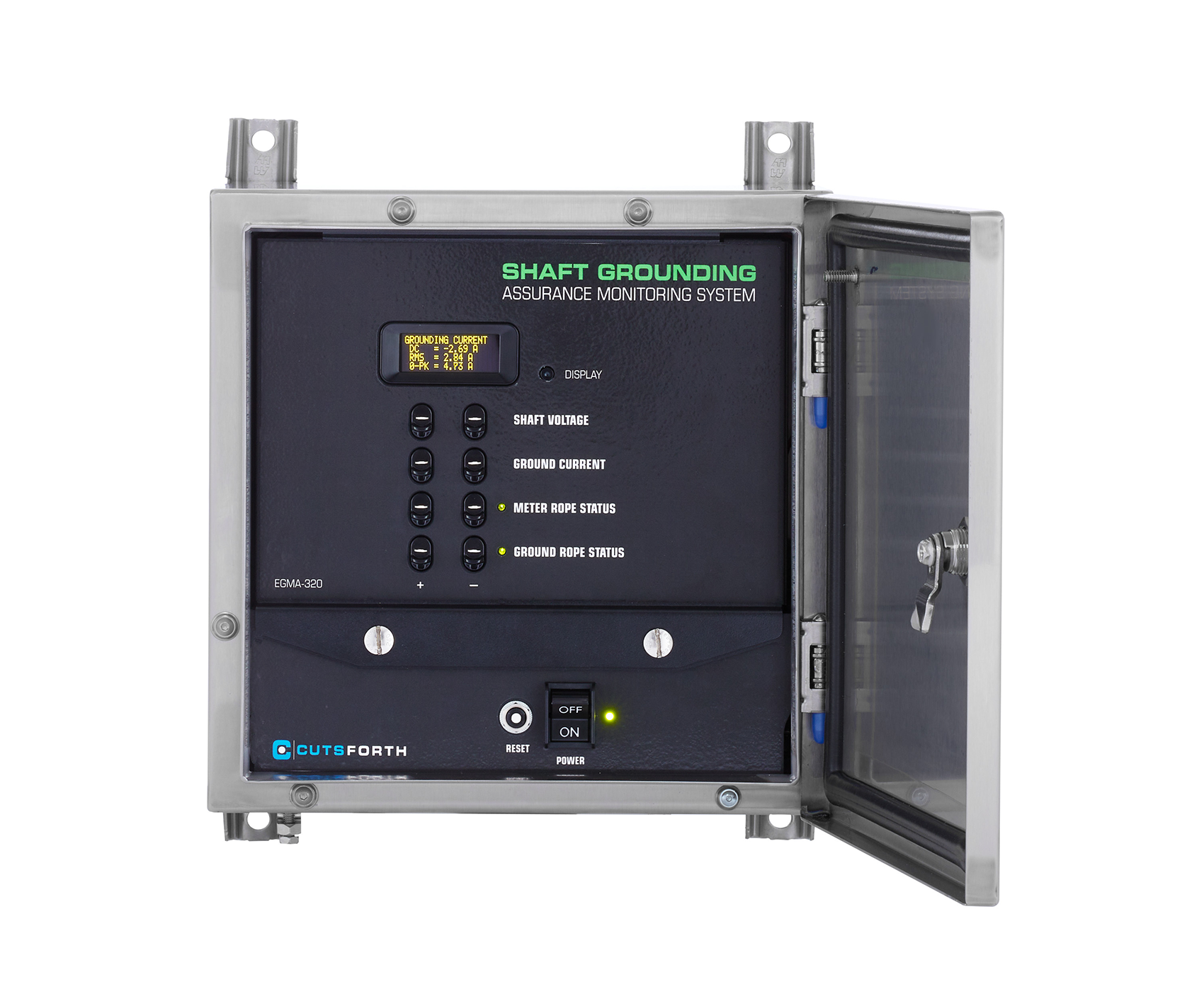
- Easy to Read Display
- Measures and Displays the following in real-time:
- Voltage
- Current
- Ground Rope Status
- Connects to Plant Control Systems via Modbus TCP/IP or RTU
- 4-20 mA connectivity also available
- Safe and simple installation
- Easily connects to Cutsforth™ Grounding Assemblies
Shaft Ground Monitoring: Premium System
Learn more about our next tier Shaft Ground Monitoring: Premium system with built-in oscilloscope functionality, event based waveform recordings, and more.
Learn more